
Machine learning, engineered on top of real CFD
Vortic CFD builds machine learning around a specific problem: predicting how a design will perform before it's built, working out where to place a sensor, searching hundreds of design variants automatically, or training a control system that reacts to changing conditions in real time. CFD generates the data. This is what gets built on top of it.
Predicting performance and searching a design space
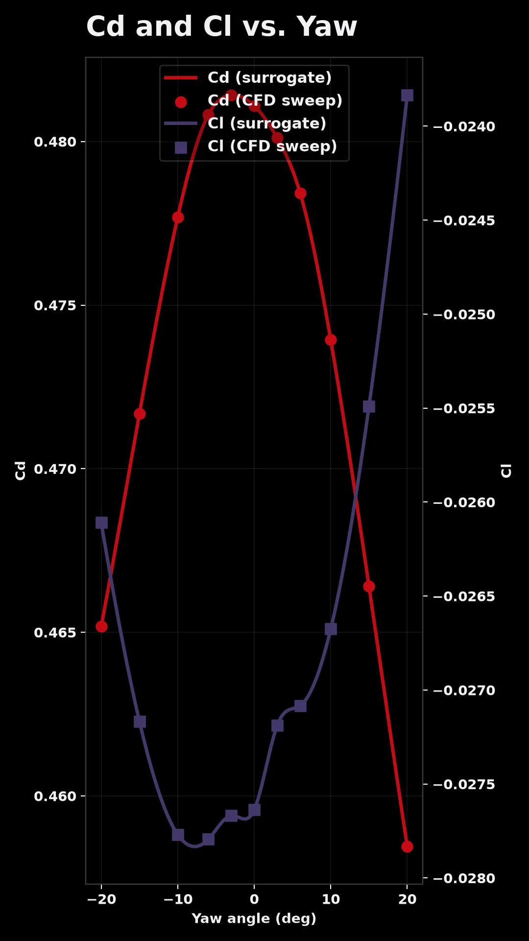
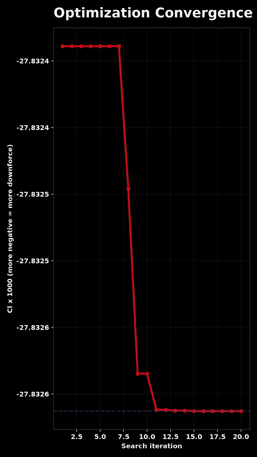
This is what gets used once manual exploration hits its limits: too many design variables to test by hand, or a gap between a good design and the best one that's worth the extra effort to close. A model trained on your CFD results (a surrogate model) can predict how a new variant performs in seconds instead of hours, which is what makes searching hundreds of variants practical.
- 01
Design-of-experiments exploration
Systematically sample the design space instead of one-off manual runs, so the studies that get done are the ones that matter.
- 02
Surrogate / reduced-order modeling
Train fast approximate models on CFD results to explore variants without a full simulation for every single change.
- 03
Automated optimization loop
Search the design space in a closed loop, using CFD as the evaluation function instead of stepping through it by hand.
- 04
Custom tooling for the problem at hand
Bespoke scripts and pipelines built around your specific workflow.
Where to put a sensor
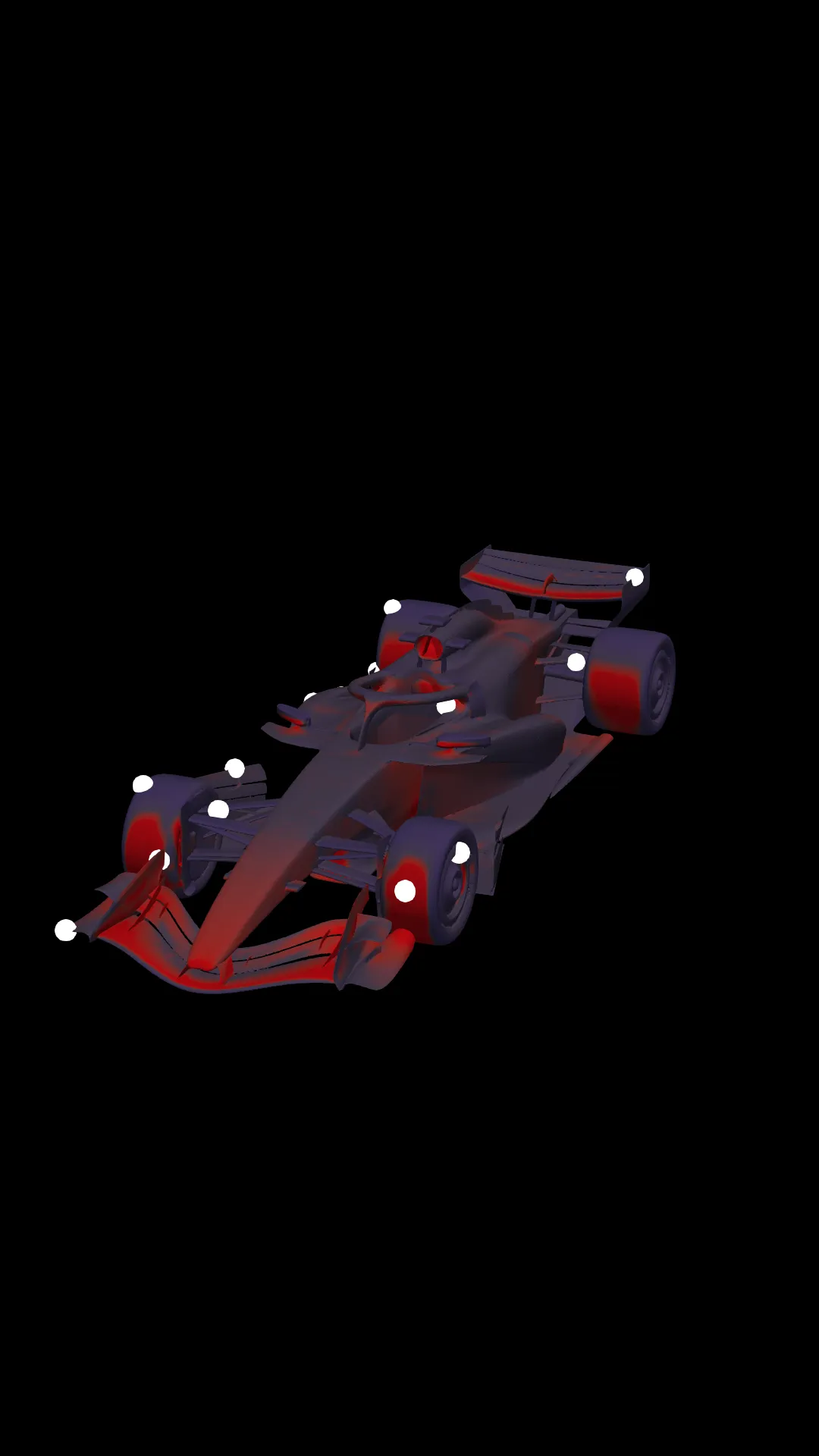
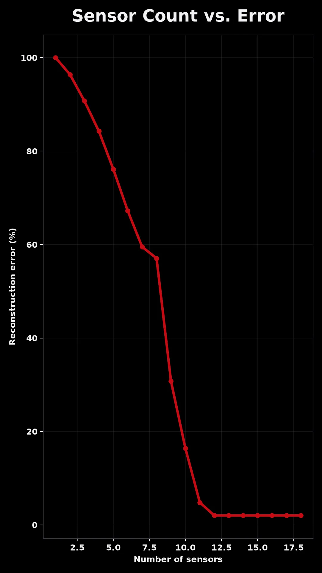
Instrumenting every point on a surface isn't practical, and most of it is redundant anyway. Given a handful of CFD-generated fields, a sparse sensor placement algorithm picks the locations that carry the most information, and drops the rest.
On the existing full-car study, that comes down to 18 locations spread across the wings, nose, and floor edges, reconstructing the pressure and shear fields to within a couple of percent.
Active flow control
Some components need more than the right shape. They need to react. A wing adjusting its angle mid-corner. A duct valve responding to a changing thermal load. An active aero surface reading live sensor data. Each of these is a control problem.
The process starts the same way: CFD generates the training data, and a control policy (often reinforcement learning) is trained against it. That policy is what runs on the real system, tuned entirely from simulated data before it ever touches hardware.
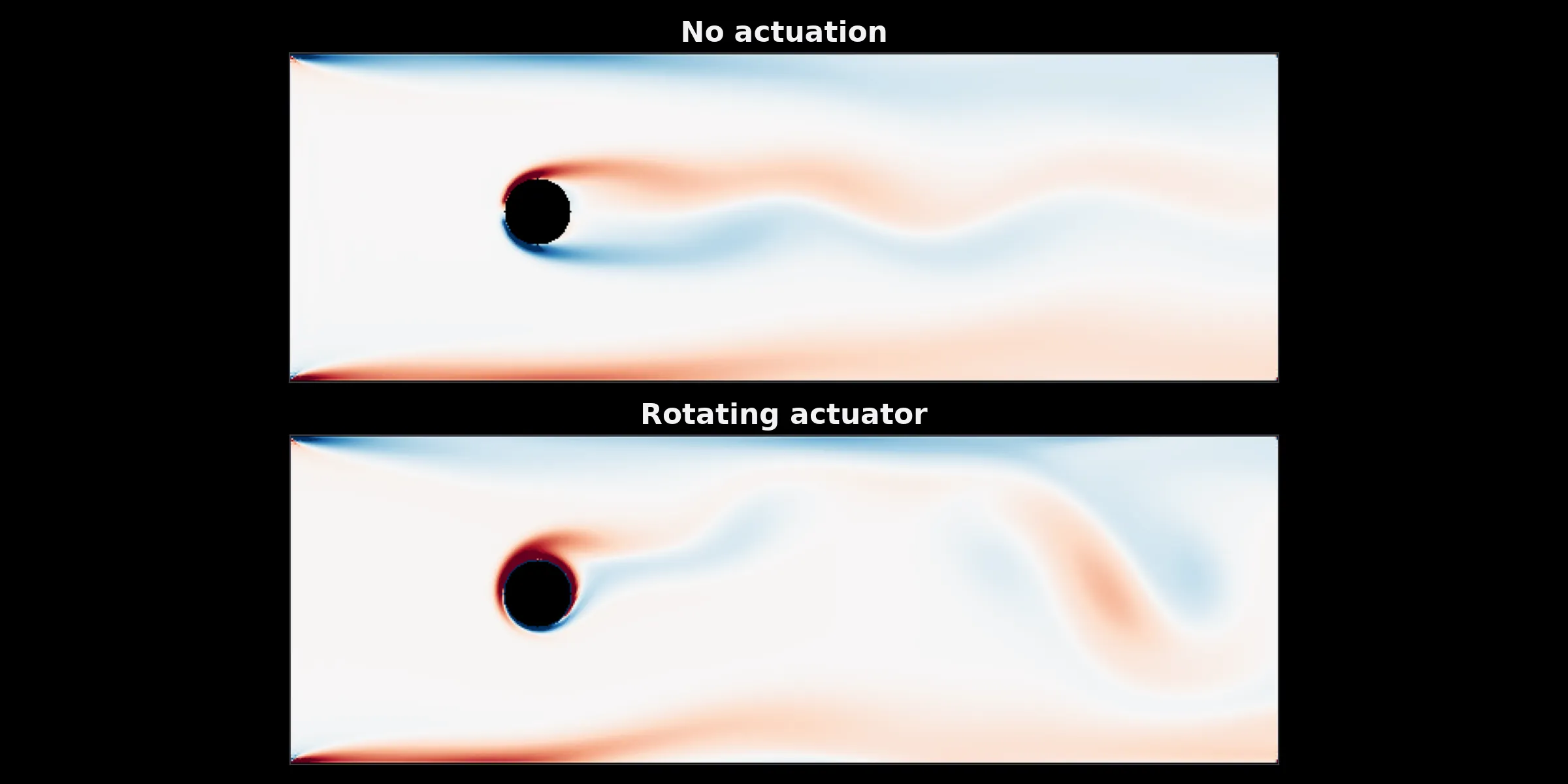
A small standalone example: a rotating actuator on a cylinder in crossflow, tested across a range of rotation rates against the unactuated wake. The actuator has real, repeatable authority over the wake, exactly the kind of closed-loop relationship a control policy is trained against.
When this gets used
Most engagements start as a straightforward CFD study. This capability comes into play once a project moves from "does this work?" to "what's the best version of this, and can it adapt on its own?" That might mean exploring a wing profile across dozens of angle-of-attack and geometry combinations, tuning a duct shape against a cooling target, placing sensors where they'll actually catch what matters, or building a control system for a component that needs to respond to conditions the original design didn't anticipate.
The output is a validated design or control policy, backed by the same CFD fundamentals as any other study, reached faster than testing every variant by hand would allow.